This is part 2 of a three-part series covering Minimum Detectable Activity (MDA) time constants. It covers discrete component logarithmic ratemeters.
Part 1: Determining MDA Time Constants - Linear Analog Ratemeters
Part 3: Determining MDA Time Constants - Microprocessor Controlled Ratemeters
This article will cover response times for discrete component logarithmic ratemeters such as Ludlum Model 395's, 177-50's, 333-2 Air Monitors, 3502/3503 Gate Monitors, and Model 300, 300-9, and 355 Area Monitors.
Calculating meter response times for logarithmic ratemeters is somewhat more difficult than the linear ratemeters described in the previous article — log-ratemeter response time may vary from 2 minutes to less than one second. There are several variables which affect the meter response time of the log-ratemeter circuit: the integrating capacitor used to filter the pulse rate; the incoming pulse rate relationship to the meter dial decade (lower, mid, upper decade); the beginning reference of the response measurement — measured from zero to midscale, lower to mid, zero to upper, etc., and whether a RESET has been initiated before the response time measurement.
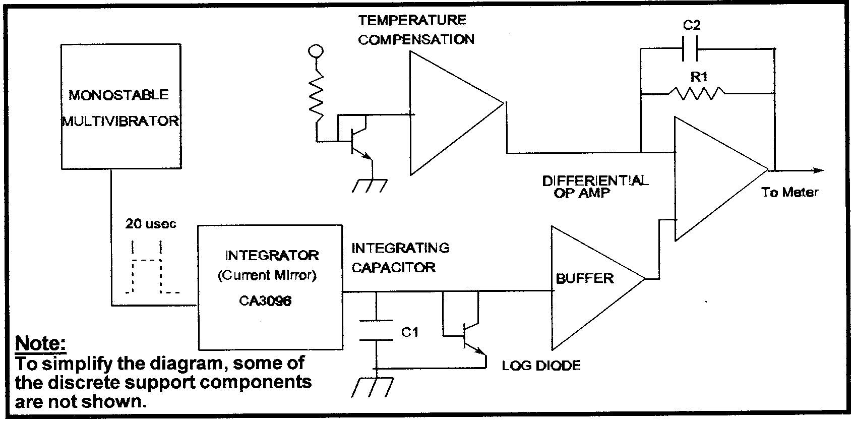
The Model 395 log-ratemeter circuit will be used for discussion:

Amplified detector pulses are coupled to the monostable multivibrator. The pulse width output of the multivibrator is fixed at approximately 20 µs. The count rate on a four decade meter dial at 1/4 full scale (first decade) will equal approximately 120 cpm.
The 20 µs pulse width equates to 0.004% duty cycle for the 120 cpm pulse rate — the current sourced in to the log diode is equal to approximately 0.1 µA. This current will increase by a factor of 10 for each decade with full scale at approximately 100 µA.
The time constant is calculated by dividing the voltage dropped across the log diode (measured at buffer output) by the current for the particular decade to obtain the approximate resistance for the R x C calculation.
Example: The Vdc at the buffer output equals 0.46 at 1⁄4 full scale, divided by 0.1 µA gives an approximate resistance of 4.6 megohms. The integrating capacitor is a 22 µF — (22 x 10-6) x (4.6 x 106) = 101 seconds (1 time constant = 63% of the full charge). With integrate current increasing by decade — 1 µA: 10.1 seconds, 10 µA: 1 second, 100 µA: 0.1 seconds.
Note C2 and R1 (4.7 µF and 165k ohms respectively) on the differential op amp feedback in the illustration — when the response is below 1 second (3⁄4 decade and above for the example) the time constant of these two components override the logarithmic integrator.
The example above is calculated from zero (C1 completely discharged). If the response time is measured from, say background, the response will be faster. Some of the log circuits have the reset components tied directly to the integrating capacitor which shunts the signal to ground when a RESET is initiated; therefore, whether the response is measured after a RESET or radiation background can make substantial difference. In conclusion, with all of the variables associated with the logarithmic time constant/response time measurements, the most efficient method is to measure the operating region of interest at the 10% and 90% points of the final reading.
